My Slatgrill body project
I sold MB 227209 in about 1992, and began doing a slatgrill. While family obligations have forced me to suspend my effort until recently, I have during all those years continued to collect parts when traveling on business in the US and Europe, do the requisite machine work on the engine, and rebuilding the drive train. Consequently I have collected an eclectic mix of NOS and reproduction parts and body panels from several manufacturers. Most of this slatgrill project is ready for assembly, and in my retirement I finally have the time.
As mentioned elsewhere, Merrill Madsen (co-author of AAW) scolded me in 1989 for not replacing late style front floor hat channels with early on MB227209. In homage to Merrill, I am tweaking or building all the individual panels to match both the original panel dimensions, fit, and features (tapping plates, captive nuts, etc.) exactly, and checking that they are true to the Ford GPW drawings published by the Henry Ford Museum as well as JeepDraw drawings, within at least 0.1″.
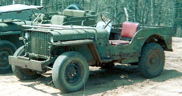
Glovebox Satgrill, Feb 24, 1942, as found:
Here are some pictures of my recent work, and issues I have found (click to expand):
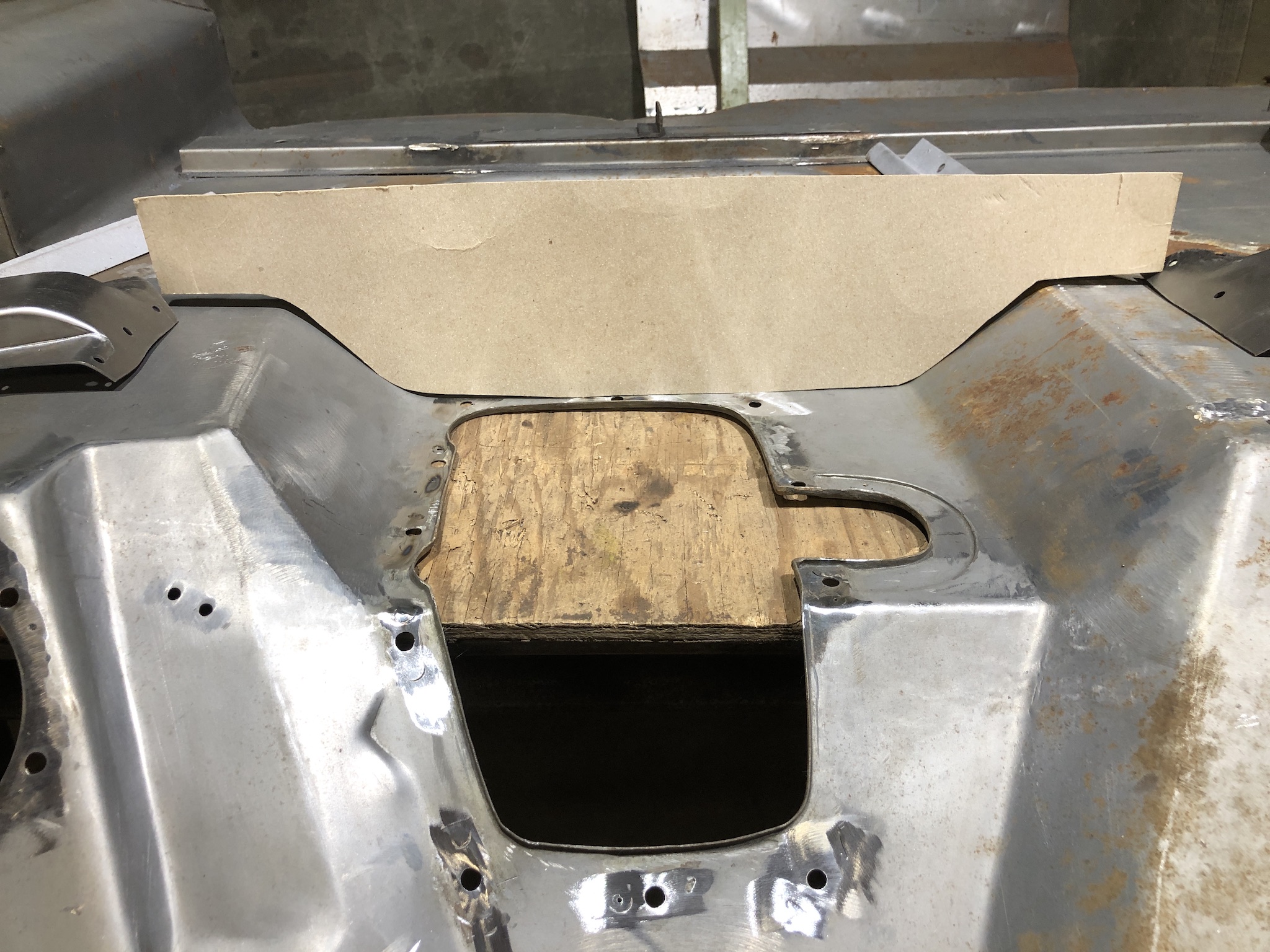
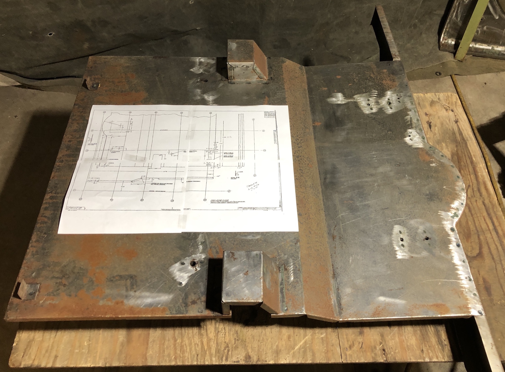
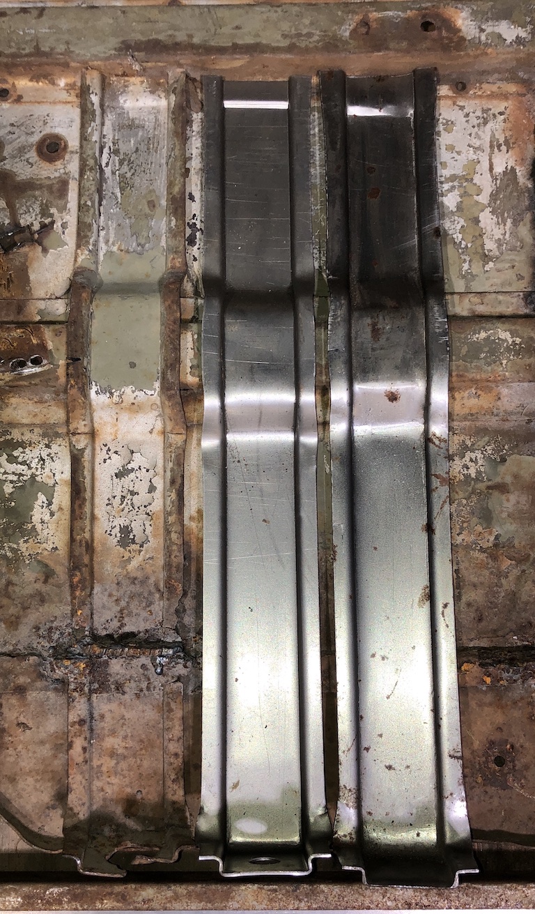
Template to check hump shape and depth of MDJ floor I am using made from original floor
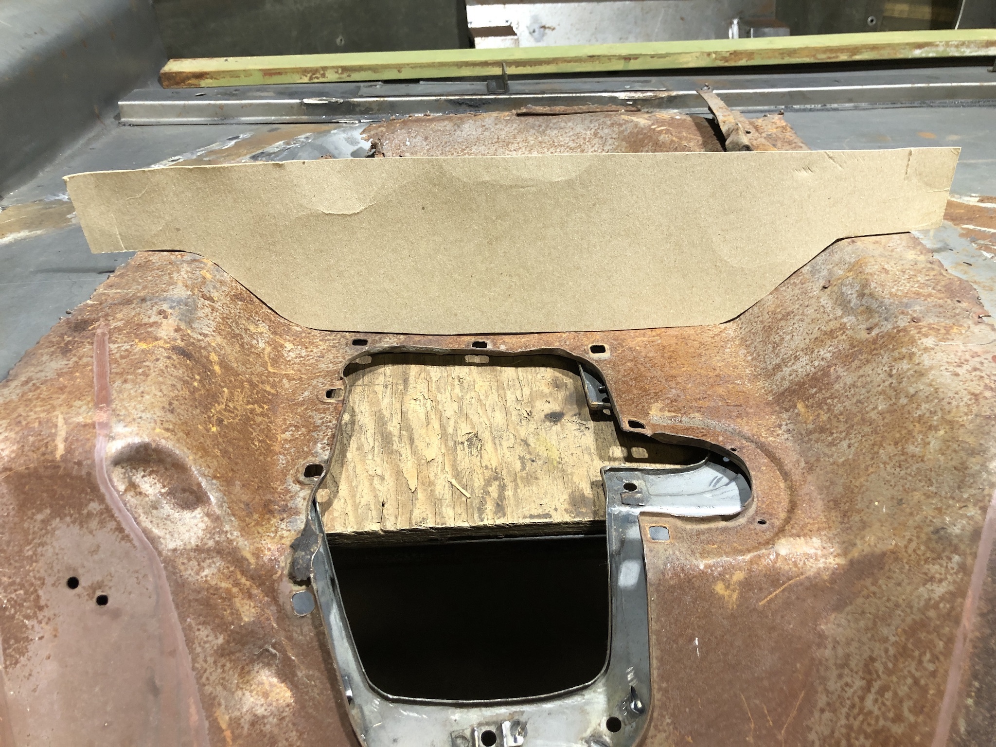
New floor matches template fairly closely, except seems about 3/8″ shallow and around 1/2″ to 3/4″ in wider at bottom. So the transmission hump is close to correct, and there is not much that can be done to change this anyway. Old floor is a full 0.0479″ (18 Gauge), while the new floor is more like 0.0430″, which I deem acceptable. BTW, the download of the large Ford drawing of the front floor is unreadable, however, if you zoom in on the drawing on the Ford website and take screen shots of that you can assemble a very readable full drawing from 6 or 9 screen shots, some snipping and scotch tape.
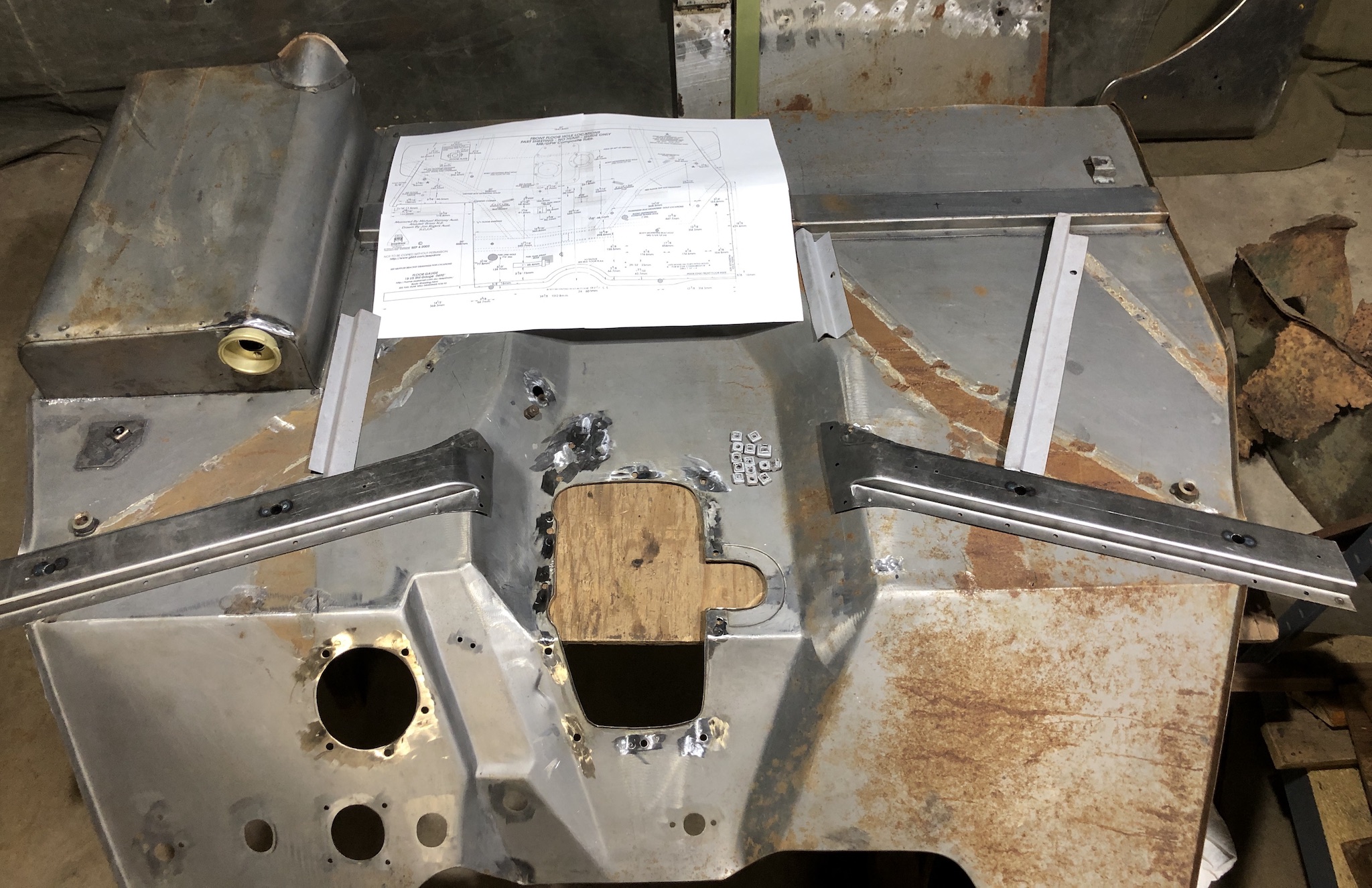
From what I can tell, there are three manufacturers that make full front floors, MDCAB (a.k.a. STIC in Sancerre France), MD Juan (in the Philippines) and recently SGI (from India, which I don’t like, it appears to have a major incorrect overlapping seam added at the toe board bend…). All others reuse the transmission hump from an original floor because a full floor requires a very large press and fancy tooling to make (actually not a bad strategy, since with careful MIG and grinding you can’t see the seam.). The floor I am starting from came from MD Juan via DL Bensinger many years ago. In my opinion all these floors are full of small issues, but most can be fixed with some elbow grease, a MIG welder, an angle grinder, and attention to detail. The fuel sump attached to this one appears to have the correct shape and dimensions. To make this assembly be a close match the original floor I am fixing the following:
- Caged nuts around transmission opening need to be changed to early style (can be removed from the old floor with care and reused, after squaring and dimpling holes).
- Replace the steel fuel tank sump drain sockets with the brass originals removed from original floor, and solder.
- Bend outside edge of sump down, current is up and incorrect (use heavy square steel bar as a spacer and lots of clamps to do this)
- Remove suppression strap stud, and install original from old floor, moving it forward about 2 inches to match original position.
- Remove ACM2 Composite hat channels, replace with proper die formed ones from Midwest Military which are exact ACM1 style (See: die formed) (unlike what I see others doing where they just fold, weld, and grind, see: SGI ACM1, also note incorrect seat tapping plate, incorrect gas tank strap reinforcement, and incorrect caged nuts on the SGI floor for an early MB.)
- Move drivers seat tapping plate and gas tank strap reinforcement from old floor to new
- Add hole for fuel line
- Move and weld rear fuel tank strap bracket from old floor to new.
- Remove several spot welded harness clips, early floors use screwed in clips except in one or two spots
- Trim length at riser during assembly to rear floor
- Check position of all holes against JeepDraw and Ford diagrams to be within about 0.10″, drill as necessary.
- Move the muffler hanger and caged nut to the new floor.
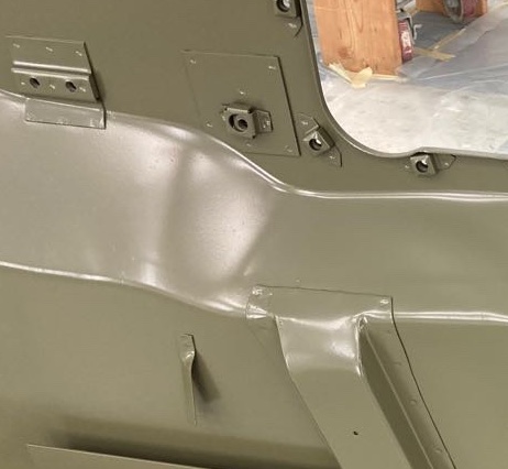
- Not too happy with the radius of the big bend up to toe board, too sharp compared to an original, also radius in the lower area of the accelerator pedal is too box like, I might flatten this slightly with a little heat, peening, and grinder work.
- Slight depression at rear edge next to fuel tank sump is missing… will press that in.
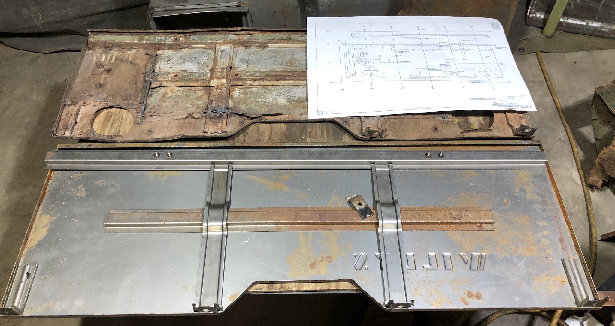
Rear floor I am using is a little thicker than 0.049 ” 18 Ga original, at 0.0530″. Have to replace middle hat channel that was about 3/16″ too narrow (replacing with Gesink made one that I had). Have to remove captive nuts, as I believe early MBs use loose nuts on foot rests, otherwise all dimensions match Ford drawings exactly. I think this is a GENMARC made in the 80’s.
Rear panel, using old as guide, and checked against original Ford and Jeep Draw drawings. Had a good quality GENMARC reproduction which I sold as hat channels still not up to my pickey requirements. Had a plain skin made for me by Classic Enterprises in Rice Lake WI out of real 0.049″ 18 Ga., with excellent Willys embossment that exactly matches original embossment. (They told me I think that they have permission to use the Willys and Ford logo on these.) Purchased upper hat channel and vertical reinforcements from Midwest Military in Prior Lake, MN… all excellent and exact. Using intermediate hat left over from John Gesink stuff I had. Using original starting crank bracket and corner handle reinforcement plates removed from original rear panel. Wondering how to make the tail light holes, perhaps careful use of a fly-cutter…. Overall result should be a perfect copy of original, mostly because of Midwest’s excellent pressed vertical reinforcements and correct hat channels.
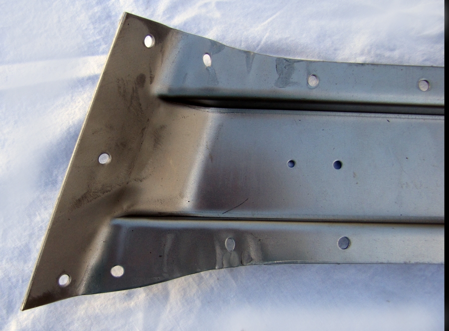
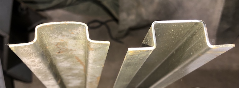
Examples of original, good (Midwest), and a bad (small shop) vertical reinforcement:
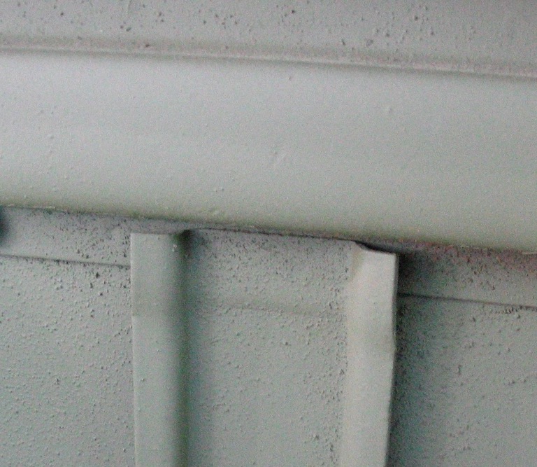
Correct original overlap:
Badly made rear panel no overlap, photographed at TowerPark, CA 2013, being sold by reputable vendor:
Badly made rear panel upper hat channel (small shop), left, and Midwest Military exact one on right w/nice square radius edges and even has studs for seat back hooks, matches original exactly:
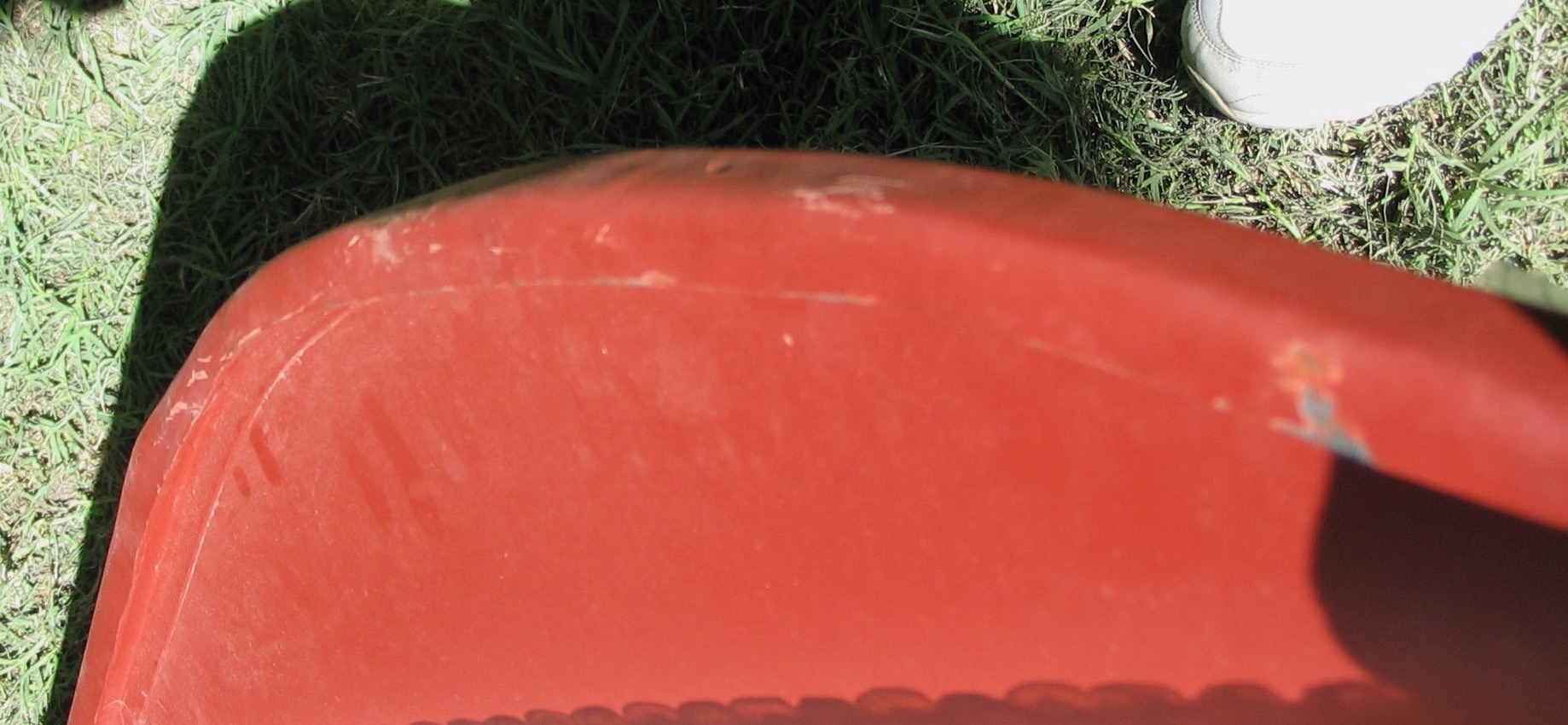
Left Rear Quarter. Using Ford GPW drawings, length seems correct at 58 1/4″, and hole positions seem good +/- 0.1″ matching both JeepDraw and Ford drawings, but wheel arch appears about 3/4″ or more too far to the rear, which will work, but front edge of wheel opening will not come up to inter-floor riser exactly. Good thickness, is 0.050″, slightly thicker than specified 18 Ga., good square radius and smooth top folded edge and U reinforcement under, but overhang a bit short at curve (see below), good smooth and correct rear corner and flange. I think this is a GENMARC made in the 80’s.
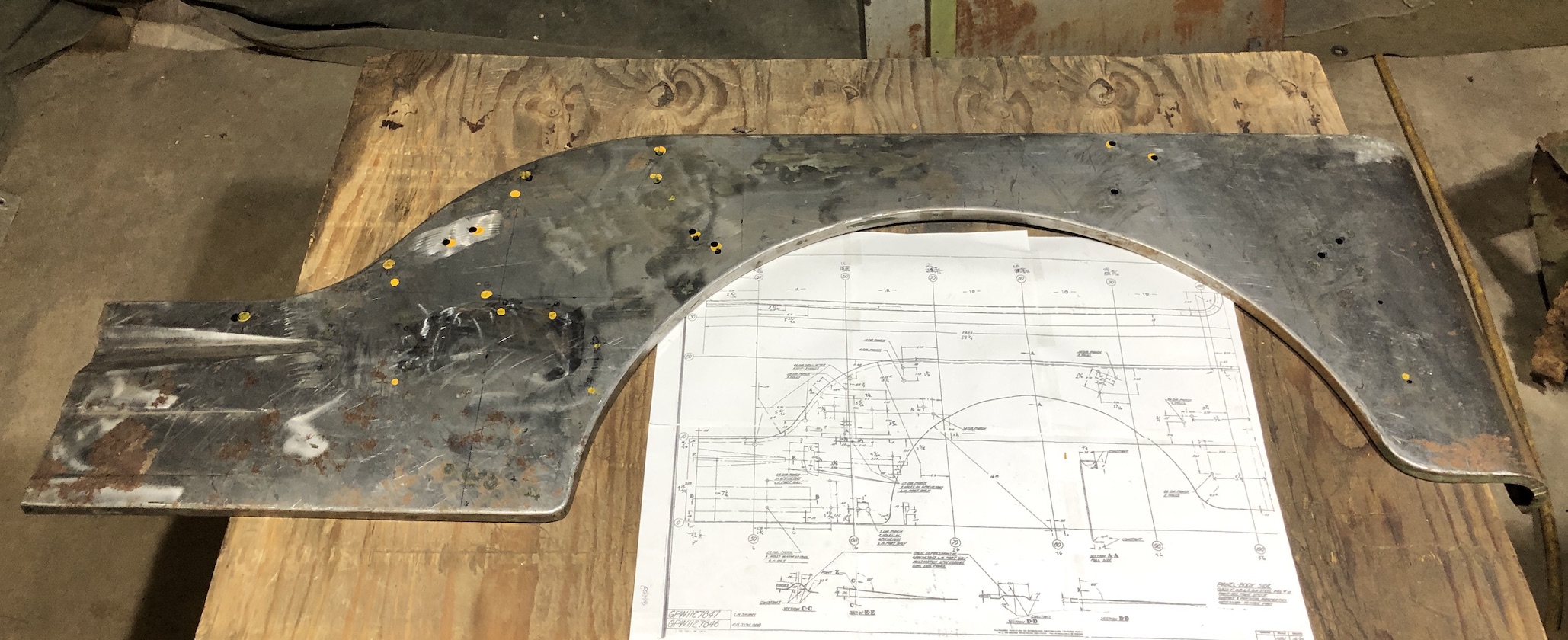
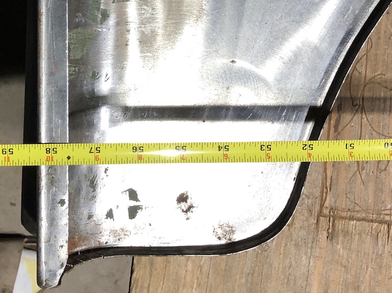
Correct overall length, 58 1/4 in, per Ford drawing and measurements of several originals, good corner curve.
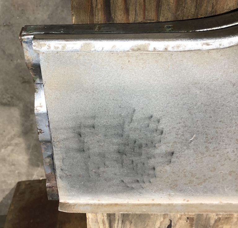
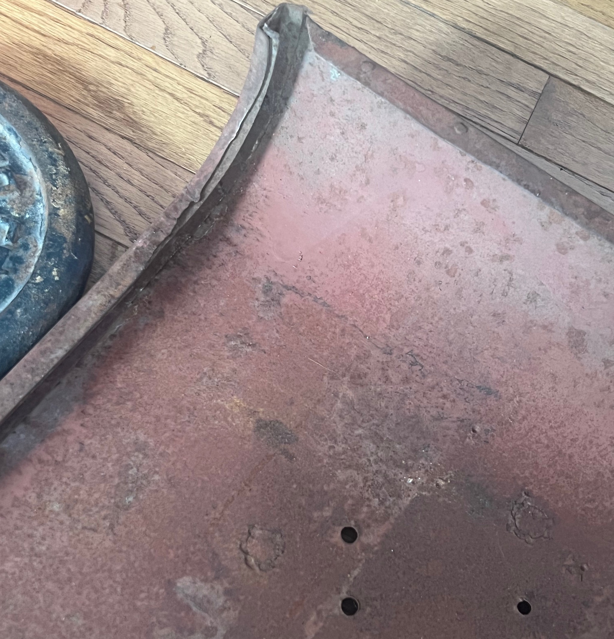
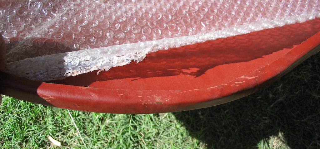
Right rear quarter panel. Steel is 0.054 thick, so thats good. Rear curve to mate with back panel is not well formed, but could be fixed. Inside edge (shown below) has cracks/gaps and is not a full 1/2″.
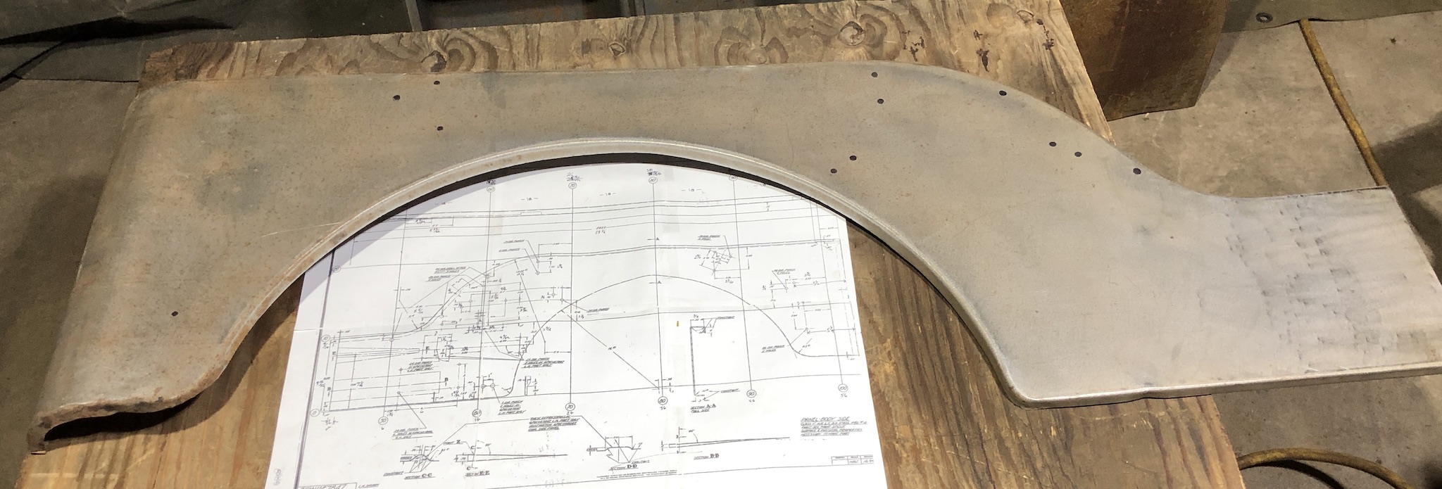
When L & R wheel arch are matched on top of each other, incorrect position of wheel arch is obvious at ends of panel. More research needed. Both R & L are slightly different than remains of my original body. I think it is a mistake to compare quarter panels from various sources and even originals, one must measure and use the Ford engineering drawings as a baseline. I made a template as a start. I am going to measure more original bodies to explore how much production variation there was in non-critical spots such as the wheel arch.
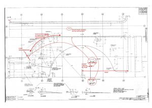
Here is a drawing with red annotations showing problem areas, and measurements one should check, click for a larger PDF:
Here are examples of good and bad rear quarter panel curves:
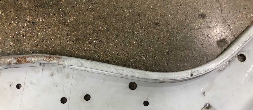
Factory, full 1/2 overhang and 3/4″ width, smooth, no split areas, nice sharp radius on the folds, how it should be
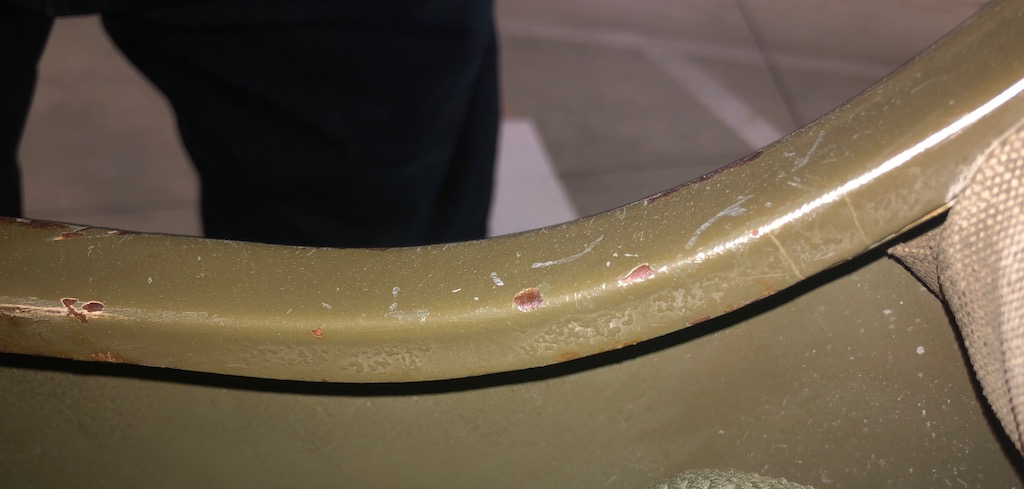
Another factory, full 1/2, smooth, no split areas
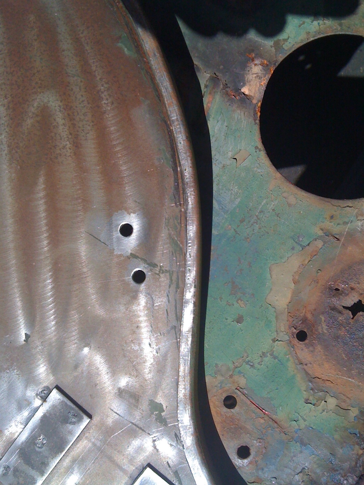
NOS repair quarter panel, unused. (believed to be real US made Willys/ACM, not Hotchkiss import):
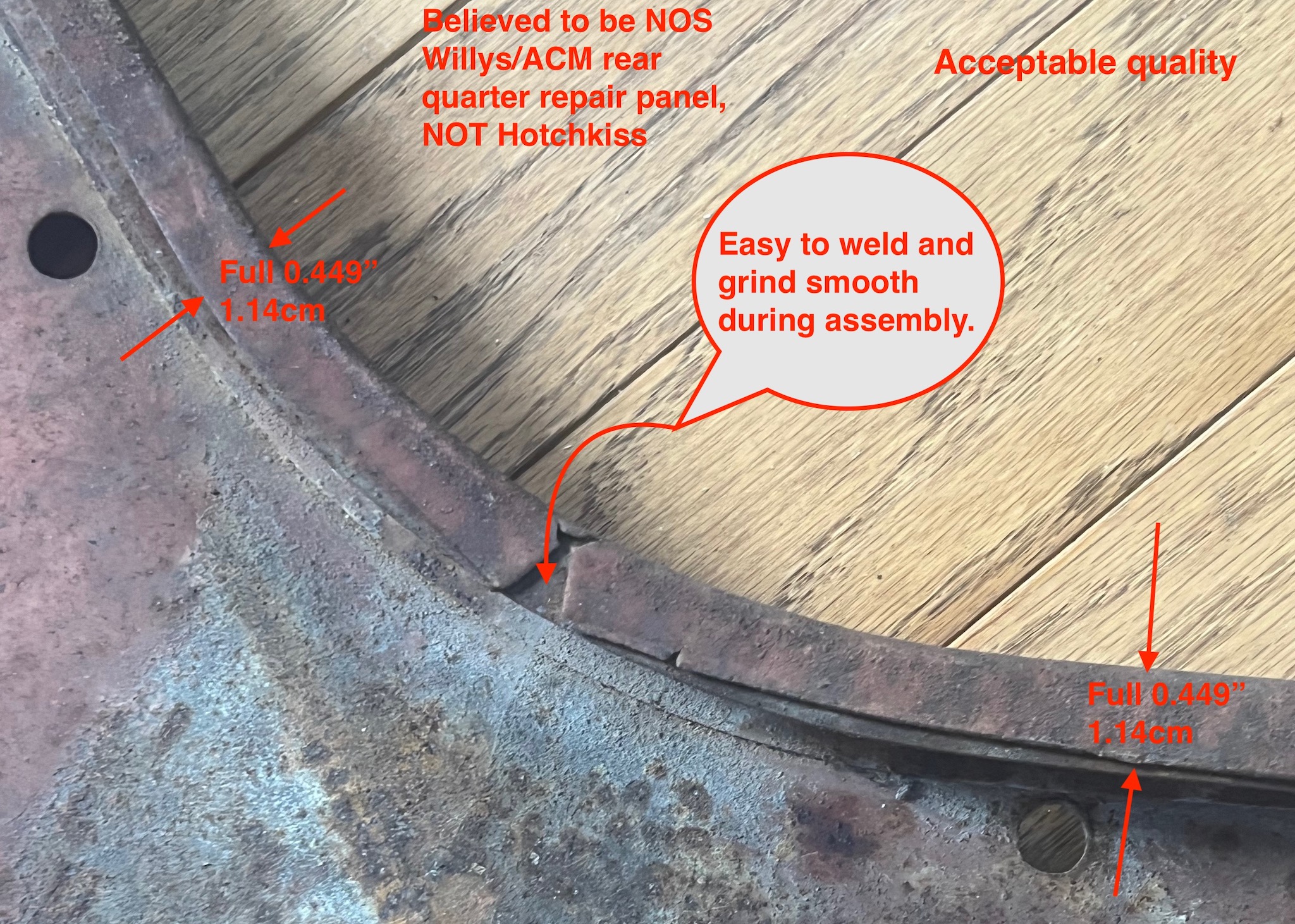
Rear corner of NOS quarter, this gap is often seen on regular production MB/GPWs:
A recent (expensive) good quality repro, looks be a bit under 1/2″, radius on folds not as sharp as original:
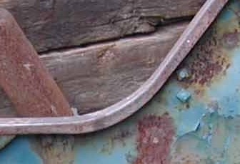
Older repro, overhang is not the full 1/2″:
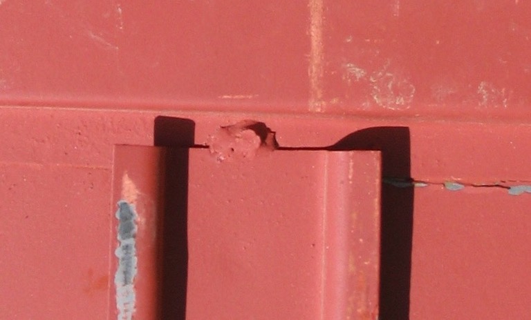
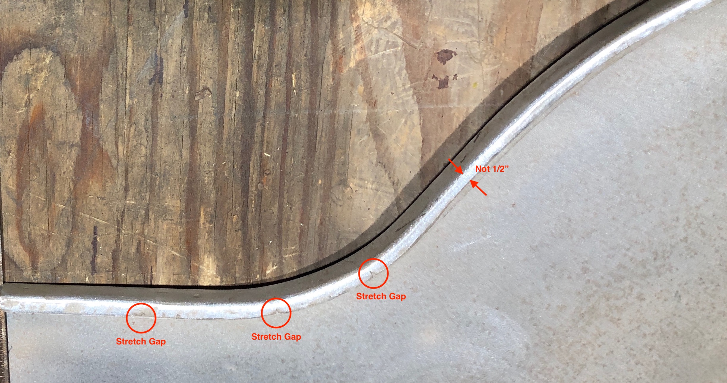
Poor quality, older panel, made in Philippines…
(they probably have improved). Note that overhang is way less than specifed 1/2″ and is obvious to the eye, and there are splits in the overhang where the metal was stretched too far.
Another example of very badly made rear quarter panel, sold by a reputable vendor, photographed at TowerPark about 2013:
Note that the radius on the folds are not sharp…you can see it a mile away, yuck!
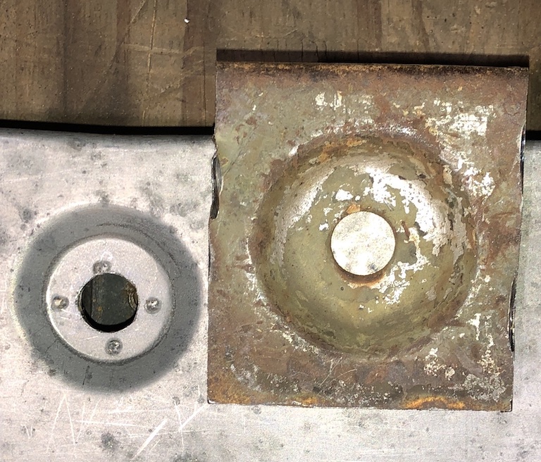
Tool box lock depression incorrect on wheel houses I have (I think they are older MD Juan)… not sure how I am going to fix that yet but probably careful cutting, MIG welding, and grinding… or buy other panels from JMP or the French.
Conclusion:
So, my opinion at this point is that only the French panels originally made for the French Army, probably with the original Willys/ACM tooling, to the original drawings, are exact. See my writeup on these MB 227209 body I built in 1989 using French panels (Not sure about French M201 front floors however at this time, have to see some original Hotchkiss M201 floors, Hotchkiss may have taken some shortcuts to save on the large press and large tooling required.) The only place to get these panels is from a French retailer who talks STIC/MDCAB in Sancerre to do a production run on occasion.
02/13/24 – Sad news. I spoke today with the director of MDCAB, and he told me they can no longer produce MB/GPW/M201 body parts, as they recycled/destroyed all the original Willys tooling some time ago.
Back to my MB/GPW site home page: MB/GPW Home page